Links Fixed 20 Feb 2016 11:35 AM (9 years ago)
 Sincere apologies if you haven’t been able to access the site, all posts should now be working!
We’ve also updated the site so hopefully it will work better on mobile devices.


PlexiMods now on Twitter! 24 Jun 2010 8:19 AM (15 years ago)
 I’ve opened a twitter account for PlexiMods which will automatically tweet with a link to any new site update. The address is http://www.twitter.com/pleximods, click follow to keep up with any site updates or to get in touch!
I know the site hasn’t been updated in a while, I’ve been quite busy with work on other sites developing them so haven’t had time to do much myself. I *was* hoping that other people would want to contribute mods and articles to PlexiMods, but I’ve had nobody contact me yet about doing so? Get in touch if you’re interested in sharing!!
Draining The Filter Caps 27 Feb 2010 1:31 PM (15 years ago)
DO NOT touch anything inside your amp chassis before doing this!
In your amplifier the filter capacitors (the large cans that stick on top of the chassis, sometimes the preamp one is board mounted) store voltages long after use, so this voltage needs to be drained, if not it can KILL.
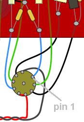
This diagram shows the first preamp tube in a Marshall Plexi, in a normal Marshall Plexi it’s the one closest to the side edge of the chassis, and furthest from the power tubes.
Start by connecting an insulated crocodile clip to pin 1 of the tube socket, denoted by the grey line on the diagram. Connect the other end to a suitable grounding point, which in this case will be the chassis. Turn the mains and standby switches on. The voltage should drain in around a minute, but most people prefer to leave the crocodile clip connected to ground, as capacitors can re-grow voltage (like batteries)! Make sure you check that there’s no/negligible voltage left before you get to work on the amp.
Never short out the filter capacitors directly.
– Richard Baines
Bleeder Resistors 27 Feb 2010 1:19 PM (15 years ago)
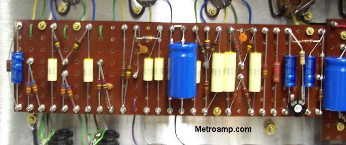
One useful modification to add to an amp is to add 330k resistors in parallel to ground with all your can filter capacitors. By adding these the voltage automatically drains from the filter capacitors in minutes, and theoretically this reduces the need to drain the capacitors before working on the amp. These resistors have to be added to the amp anyway if you install Power Scaling, so if you plan on installing that at some point you can get it out of the way now and have a safer amp to boot.
 <– here’s how to wire the resistors
However; don’t rely on the resistors to do their job – although it makes the amp much less likely to retain voltage, it’s still advised that you continue to drain the caps too with alligator clips just as an extra precautionary measure. If you’ve ever been shocked by an amp with residual voltage, you’ll agree that it’s worth spending the 30 seconds to do it.
I’d advise using metal film resistors for this job, rated for at least 2 watts. If you can get 5 watt resistors, that’s even better.
Copyright © Richard Baines 2006
Tone Stack Lift 27 Feb 2010 1:17 PM (15 years ago)
If you’ve ever heard of ‘no-load tone controls’ or removing tone controls completely for a guitar, this mod is pretty similar, but for an amp. Basically it involves lifting the wire going from the middle pot to ground, thus taking the tone controls out of the amp’s circuit.
You could make this a permanent modification if you like the sound, but a far more useful solution is to make one of the amp pots have a second function as a SPST switch, and wire this mod to it. Just replace any of the tone control pots with a push-pull pot that has the same resistance value and taper, connect it up as normal, then use the two contacts of the switch to interrupt the mid pot’s ground connection as follows:
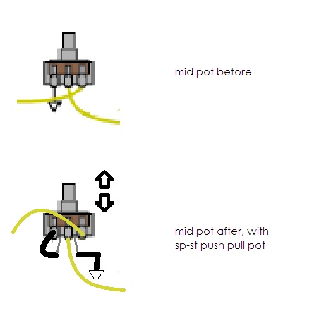
You don’t have to make the mid pot the one with the switch, but do make sure its the mid pot’s ground that you’re interrupting when you install this mod.
The results are what sounds like an increase in gain and a slight difference in feel, and obviously the tone controls become redundant.Those looking for an EVH brown sound like tone might find this mod particularly useful, and its nice as it is very simple to perform, and easy to engage. Here’s a soundclip courtesy of Kevin Andrigo:
soundclip
text and images Copyright © Richard Baines 2010
Switchable Tone Stack 27 Feb 2010 1:15 PM (15 years ago)
The two main tone stacks used by Marshall over the years was first the 56k slope resistor and 250pf capacitor combination – this was used exclusively until 1968 on all their amps. Later on Marshall started using the 33k/500pf combination, and this is the one used on the 1959slp, 1959HW and 1987x reissue amps and basically all their flagship Lead models since 1968.
Some people associate the 56k/250pf with the “classic Marshall tone” as it was used by Eric Clapton on his early recordings, The Who when they first got their hands on Marshalls, and even Eddie Van Halen’s “magic Marshall” is said to have used this tone stack. However, it’s also been said that until Marshall started using the 33k/500pf combo, Jimi Hendrix had all his amps worked on to put this combination in. Even more important though is what sounds best to you, and what better way to find out by being able to switch between the two with the flick of a miniswitch. Therefore, I’ve worked up these diagrams to make installation of the switch a cinch. Use whatever wire colours you want, I’ve just used whatever seemed to make the diagram clearest.
Method 1
First off is the most obvious way of doing it, and with each setting you will only be using one resistor and one capacitor. Some people might prefer this setting in case they’re using carbon comp resistors and want to maximise resistor distortion, or want to keep the circuit physically as well as electronically the same in each setting. The downside to this method is that you may get a popping noise when flicking the switch, as for a split-second the switch is breaking the contact between the resistor/capacitor and the rest of the circuit.
click the thumbnail to enlarge the diagram
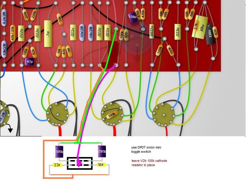
Method 2
The second diagram shows the other way you can switch between two tone stacks, by adding components in parallel with the tone stack on the board. For this to work, you must be using 56k/250pf as the tone stack on the board, and use 82k and 250pf for the parts mounted on the switch. By putting the two resistors in parallel (56k + 82k), you reduce the value of the resistance to 33k, and by putting the two capacitors in parallel (250pf + 250pf) you achieve the capacitance of 500pf. Because in this method there is always a resistor and capacitor connected to the rest of the circuit, you eliminate any switching noise.
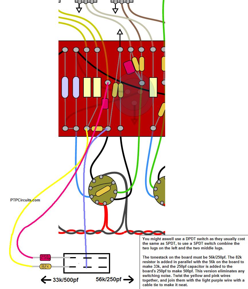
click the thumbnail to enlarge the diagram
Copyright © Richard Baines 2006
Connecting a Marshall reissue effects loop 26 Feb 2010 7:02 PM (15 years ago)
Whether you’ve installed a Metroamp PTP board in your amp instead of the printed circuit board, or you’ve bought one of the Marshall effects loop boards separately from your local Marshall distributor to retrofit into your amp, this is a quick and easy guide on how to fit your effects loop.
Let’s start by naming the wires. Each wire should have it’s code silk-screened next to it’s turret, from W1 to W4.
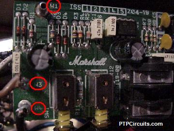
W1: Red wire, connects to 10w 47k resistor.
W2: Green wire, connects to ground.
W3: Brown wire, connects to circuit board where treble pot middle lug wire went.
W4: Black wire, connects to treble pot’s middle lug.
Basically the effects loop is inserted in-between the treble pot’s middle lug and the capacitor on the board which the middle lug was connected to (therefore it replaces the wire from the treble pot’s middle lug to the circuit board).
It’s advisable to twist together the green and black wires, and connect the green wire to the back of the treble pot or if you have a ground buss system, a point on the ground buss that’s close to the treble pot. For an even tidier job, you can also use cable ties or rubber bands to keep the two wires together. Run the two wires under the circuit board along the bottom of the chassis.
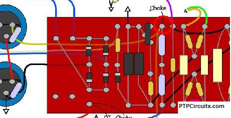
The red wire (W1) connects to a 10w wirewound 47k resistor. The other side of the resistor then connects to the voltage supply for the phase inverter and preamp, on the higher voltage side of the 8.2k/10k voltage dropping resistors where they meet the choke and screen voltage supply. On the below diagram I’ve circled the point in red for where the resistor connects to the circuit on a 100w Marshall 1959.
On the Marshall 1959slp, 1987x etc there is a special location for this resistor on the main circuit board, as you do not want this resistor hanging around in the air; it will be carrying between 300v and 400v, depending on how high your plate voltage is. If you don’t have anywhere on the main circuit board to put the resistor, I’d advise on creating a new small circuit board to mount it and run a wire from the 8.2k resistor to the resistor.
Copyright © Richard Baines 2006
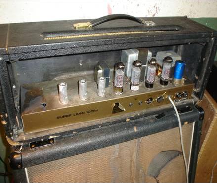
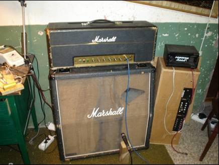
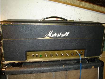
JTM Series Gallery 26 Feb 2010 6:26 PM (15 years ago)
- Hendrix’s #1 Amp, the ‘Dickinson 45/100’
|
|
click the thumbnails to enlarge the images
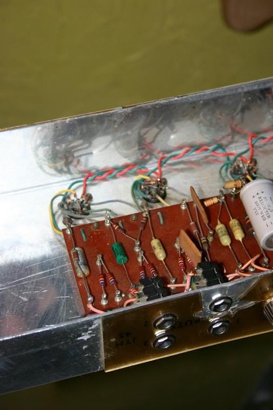
- JTM Series board – JTM Board – courtesy of George from Metroamp.com
- JTM 100 main board – JTM 100 Circuit Board – courtesy of George from Metroamp.com
Super Lead / Bass Diagrams 26 Feb 2010 6:15 PM (15 years ago)
(Plexi / Metalface)
- EVH 12000 Series Marshall
Here’s 3 simultaneous diagrams of an EVH type 100w Marshall in a moving .gif image format by Mike Cicciari, keep an eye out for the different component values.
- 1959T 100w Super Tremelo
Although not strictly a Super Lead/Bass I think it’s better suited here, since after all it’s just a SuperLead with a tremelo circuit attached. Thanks to SDM for drawing up this brand new diagram for PTPCircuits.com!
![]() click the thumbnail to see the diagram
click the thumbnail to see the diagram